
While most people have no idea what is inside the control box of a metal detector, many actually misunderstand what is in the sensor at the other end of the boom and how it works. In this article we take a look inside!
Electromagnetism
Many detectors refer to the coil as an antenna. This is not the case, at least not in the classic way of using antennas. Like an antenna, it converts electrical current into electromagnetic (EM) energy and vice versa. But the electromagnetic energy produced by an antenna behaves differently depending on how far away it is. There are usually two areas: near and far. The transition between the two areas is gradual, but mostly occurs within a wavelength. In any of these regions, the electromagnetic energy weakens as it moves away from it. This is because the energy spreads out into larger and larger spaces1. In the far field, the electromagnetic energy decays as a function of 1/d2 (where d is the distance), as would be expected from basic algebra where the surface area of a sphere is proportional to r2 (the radius). Strange things happen in the near field and the energy drops as a function of 1/d3. This is much worse and I will give you two guesses as to what area the detector loop2 is operating in. Why? Well, look at the wavelengths we're working with. Let's take a typical 10kHz VLF – the wavelength is the speed of light divided by the frequency, or
The answer is 30,000 meters, or about 18-1/2 miles! According to classical antenna theory, elements such as dipoles and ring loops are most efficient at transmitting energy when their dimensions (length or circumference) are equal to a quarter of the wavelength. In our case, we'll need a loop about 1-1/2 miles in diameter. Not suitable for precise location determination. As an alternative, consider the classic Yagi-Uda TV antenna that hangs on many roofs. The VHF band of the low frequency channel is about 75 MHz, so the length
waves is

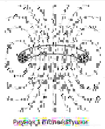
or 4 meters, and a quarter wavelength is 1 meter. This allows for a reasonably sized antenna, and indeed it is the size of a regular television antenna. Obviously, our coils are far from the optimal size for propagating classical electromagnetic waves (VLF), and that's not really what we use them for. That is, we are not interested in propagating (or receiving) a wave over a distance of several miles. We use it more as an inductor and look at the magnetic field distortions up close. Most loop coils are wound like thin donuts using several turns of insulated wire. If you pass current through such a coil, it will create a field as shown in Fig. 1.
Direct current (DC) will generate a static magnetic field, and alternating current (AC) will generate an alternating magnetic field. We are interested in the alternating current field, which for simplicity we will call the electromagnetic field. When we bring the second coil closer to the first, the signal from the first coil will be transferred to the second coil through induction. Induction is incredibly useful, and that's how transformers work. The effectiveness of inductive coupling depends on several factors, such as the placement of the coils and the core material on which they are wound. Transformers use iron or steel to improve coupling efficiency, and metal detector coils use air. If you hold a piece of metal close to a field, the electromagnetic energy will cause circular currents in the metal, known as eddy currents, which in turn create a return electromagnetic field. So now we have a transmitting coil producing an electromagnetic field, and a metal target close enough to produce a return electromagnetic field (see Figure 2).

Remember that I use the term “EM” in a broad sense; all we are really interested in is the alternating magnetic field. Now we need a way to detect the induced target field. Keep in mind that this is a very small field in the presence of a much larger transmission field, so for optimal detection we need to get rid of the transmission field. It's like trying to hear someone whisper at a rock concert. In a PI detector, we do this by quickly turning off the transmitter and “listening” for a weak target response. VLF type detectors transmit a signal continuously, so we need to do something different. As I said earlier, the second coil can be placed so that it interacts inductively with the transmitting coil. By careful placement we can also place the second coil at “zero” of the transmit field so that there is no coupling. In such a case we say that the coils are inductively balanced, and this is where the term induction balance (IB) comes from. Induction balance is the method used for what most people call VLF, TR, and even “RF” (two-unit) detectors. However, IB can be applied to PI and even BFO detectors.
Coil types
Thus, the transmitting coil creates a strong electromagnetic field; the target creates a tiny return electromagnetic field through induction; and we need a receive coil that will ignore the giant transmit field when detecting a tiny target field. No problem. The solution is to somehow “balance” the receiving coil so that the transmitting field does not inductively couple with it. There are different ways to do this, including mechanical balance and electrical balance. Let's look at mechanical methods first, since I think that's what everyone is using now. In Fig. Figure 3 shows one of the earliest methods of induction balance.
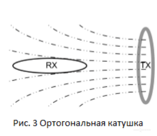
You should recognize it as a two box locator or what some people call an “RF” detector. In this case, the receiving coil is rotated 90° to the transmitting coil and placed so that it lies exactly along the isomagnetic lines of the transmitting field. Thus, no magnetic field penetrates the receiving coil and hence there will be no induced current. Inductive coupling is theoretically zero. There are at least a couple of problems with this approach. You can compress the coils and slide them onto the end of the shaft, but orthogonal orientation of the coils will result in a bulky search head. A 1969 article in Popular Electronics described such a design using three coils. The second problem is that ground balancing in mineralized soil is difficult. Once the coils move towards the ground, any mineralization will begin to compress the transmitted field on only one side and throw the balance out of whack. In Fig. Figure 4 shows another early method of achieving induction balance in a coil.

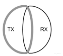
Rice. 4 ˝OO Coil˝
The receive coil overlaps slightly with the transmit coil, so that part of the inner field of the TX coil passes through the RX coil, and part of the outer field of the TX coil also passes through the RX coil. The internal and external fields of the TX coil are of opposite “polarity”, so if the RX coil is precisely positioned, the effects of the fields can be compensated for. This type of coil is often called coplanar because the TX and RX coils lie in the same plane. For a TX coil, the highest electromagnetic field strength is along an imaginary axis through the center of the coil (see Figure 1). Likewise, the RX coil is most sensitive to target signals along an axis through its center. For this type of coil arrangement, these axes do not coincide. It turns out that the area of greatest sensitivity is where the two coils overlap. Since this is not the highest sensitivity for either coil, this method has a slightly lower overall sensitivity than other methods. In Fig. Figure 5 shows a design option with an overlap, which has become very popular.
Rice. 5 ˝DD Coil˝
Parts of the coil overlap have been smoothed out somewhat, resulting in three improvements. Firstly, the overall shape of the search head is round. Second, the overlap region—still the area of greatest sensitivity—now extends from the front to the back of the coil, creating a long, narrow detection zone. Third, the highest sensitivity axes for each coil are moved closer to the overlap area, which improves depth. In this variation, each coil looks like the letter “D”, so the overall type is usually called a “DD” or “double D” coil. While overlap coils probably date back to the earliest experiments with induction (1830s) and were certainly used in the early 20th century, the DD coil appears to have been invented by Compass Electronics in the early 1970s. It is now the second most popular coil type and is almost exclusively used in Minelab detectors. In Fig. Figure 6 shows another method of achieving balance in a pancake coil. This is commonly called a coaxial coil because all the coils are located along one central axis.

Fig.6 ˝Coaxial coil˝
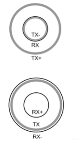
The transmitting coil is placed between two receiving coils, and the receiving coils are connected to each other so that their induced currents are canceled out. Alternatively, you can place the receive coil between two transmit coils connected to each other so that their fields are neutralized right in the middle where the receive coil is located (Fig. 7).
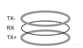
Fig.7 ˝Coaxial coil 2˝
The coaxial coil was used in early Garrett VLF machines and C&G Technology's Cat detectors, and perhaps others. I believe the C&G units actually used a modified coaxial design where the receive coils are smaller than the transmit coil. This still provides induction balance and also reduces the amplitude of the ground signal for a better target-to-ground relationship. The coaxial coil arrangement usually has a slight degradation in depth due to partial signal suppression between the “+” coil and the “-” coil. However, it has one clear advantage. Since induction balance is achieved in the vertical direction, it reduces the sensitivity of the entire coil to metal targets at the edge of the package. This allows the coaxial coil to move closer to objects such as metal fence posts without detecting them. Today, the only coaxial coils are manufactured by aftermarket suppliers. In Fig. Figure 8 shows the coplanar coil design, which was very popular in the 1970s and early 80s. It is commonly referred to as the “4B” loop and was widely used in the TR and VLF detectors from White's and Bounty Hunter.

Rice. 8 ˝4V coil˝
A small part of the transmitting coil is folded inward, and the receiving coil runs across this section. The folded part creates a smaller return field around the receive coil, which compensates for the larger transmission field. Many detectors today use a concentric coil, shown in Fig. 10.
Rice. 10 ˝Types of concentrated coils˝
Typically, if you place the receive coil concentrically inside the transmit coil, you get a mass of inductive coupling. The trick here is to add a compensating coil, which is another transmitting coil placed very close to the receiving coil. The compensating coil receives the transmission signal in antiphase and close to the receiving coil suppresses the main transmission field. The compensation coil can be placed just behind the take-up coil, inside or even directly above it. Another way to configure a concentric coil is to use a counter-receiver coil that is located adjacent to the transmitter coil, but connected out of phase, as in Fig. 10. I believe most hubs use transmission compensation. coil, but I'm not sure which placement is most common. Concentric coil from White's. One strand of wire (tied with tape) is used to fine-tune the balance. The black object is conductive rubber that is pressed against a screen that is sprayed onto the other half of the coil shell. With the exception of Minelab, the concentric coil is standard on almost all detectors. Concentric coils have the best overall sensitivity of all coil types and are relatively easy to manufacture. In most cases, the receive coil is half the diameter of the transmit coil, although this is not necessary. In some Fisher coils, the receiving coil is elliptical in shape. Garrett imaging coils have two receive coils; one is about half the diameter of the TX coil and the other is about 1/4 the diameter of the TX. The last interesting loop configuration is the “figure 8” shown in Figure 11. The TX loop is twisted into a figure 8 shape, so it produces both a positive and a negative field. When the RX coil is in the center of the crossover, it sees the same magnitude of each field and is inductively balanced. This coil configuration has two features. First, the transmission field is zero at the crossover, so in theory it will have low sensitivity at the center. Second, the transmitting field in the front half of the coil will be 180° out of phase with the field in the rear half. This means that in a phase discrimination circuit, the correct target ID will only work halfway. Figure-8 loops can be made in different ways. Also in Fig. Figure 11 shows one with an extended RX coil, which creates a long, narrow detection zone, allowing for faster ground coverage. The same figure shows an RX coil with a standard TX coil; it has the same disadvantages as the TX coil, like the figure eight. And the last one in the picture is a double figure eight, which gives the exact phase ID for the center part of the coil and with two zeros from the center.

Rice. 11 ˝Figured eight-piece coil types˝
There are many other interesting ways to create inductively balanced circuits, but these cover the vast majority that you will see on the market. With any IB coil, good balance is very sensitive to the exact placement of the take-up coil, and even slight movement of the take-up coil will upset the balance. Typically, all the coils are placed in a mold adjusted for near-optimal balance, then they are filled with rosin. To adjust the balance after the epoxy has set, one loop of wire can be left hanging and moved around, then glued into place.Ground Effect. Good balance is quite easy to achieve when the coil is in the air, away from anything that could distort the field and throw off the balance. When a metal target gets closer, it upsets the balance, which is what we want. But soil often contains minerals that also distort the TX field, and this can create an unwanted RX signal. When the coil is lowered to the ground, the soil distorts the TX field, effectively suppressing the field only on the underside of the coil. See Fig. 12.
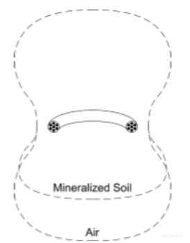
Rice. 12 ˝Ground effect per coil˝
This is not due to eddy currents, as is the case with a metal target, but due to a permeability shift, similar to how powdered iron core is used to increase the power of inductors. The top side of the coil still sees air, so the field projected upward is not compressed. For most coils this will upset the inductive balance and create an RX signal. We will call this the “ground signal” to distinguish it from the target signal. Metal detectors solve this problem by providing “ground balance” control. A full study of this technique is beyond the scope of this article, but we will do high altitude flight. Most detectors identify metal based on the phase signature of the target signal. When the coil is in the air, there is no ground signal, so when a target moves in front of the coil, the resulting RX signal will consist of only the phase of the target signal. But with a coil on the ground, there is now a constant ground signal that has its own phase, and any phase of the target signal will be added to the phase of the ground signal. Essentially, ground balance regulates the reference phase to which the phase response of the metal target is compared; those. resets the phase of the ground signal. However, it does not eliminate or even reduce the ground signal sensed by the RX coil or subsequent receiving circuitry. This means that highly mineralized ground can produce a high amplitude ground signal that can overload the receiving circuit or at least reduce sensitivity to metal targets. By now you should be thinking that the amount of ground signal produced depends on the coil design. A good design should maintain induction balance even when mineralized soil compresses the TX field. Intuitively, the coil in Figure 8 should be a clear winner, especially one like the one in Figure 16. No matter how the TX field is compressed, the RX coil will always have excellent suppression. DD coils are touted for their good performance in poor soil, which is why they are the standard coil type for Minelab reels. Australia probably has the most mineralized soil in the world. It is also intuitive that a DD coil will work well because part of the TX signal is outside the RX coil and part is inside. As long as the compression of the field does not change the ratio of the internal and external parts, the balance is maintained. But the proportions are slightly changed due to the flattened sides in the overlap area. Most likely, the “OO” coil (Fig. 4) will be even less sensitive to field compression. The most popular reel is concentric and does not work so well on poor soils. TX field compression affects the main TX coil much more than the TX4 compensating coil and results in an imbalance. Orthogonal coils perform just as poorly as coaxial coils.
Mono coils
So far, all the coils we have looked at are designed for induction balance. Some detectors do not require balanced coils. Older BFO detectors used a single circuit coil, commonly called a mono coil. In BFO, the oscillation frequency of the search coil is compared with the oscillation frequency of a small coil in the control unit, and the frequency shift caused by the metal target is detected. BFO is a thing of the past, but modern PI detectors also use mono coils. The PI detector transmits a magnetic field and then quickly turns it off to listen to the received signal. It can be obtained using the same coil. Although mono coils are usually round in shape, they can really come in any shape: oval, square5 and even triangular6. PI coils usually have low inductance and can be manufactured on a printed circuit board instead of a winding.